- ISO 9001 · CE · IEC 60076
- SGS / BV Inspection
- Shipping to 15+ Countries

Transformer Series
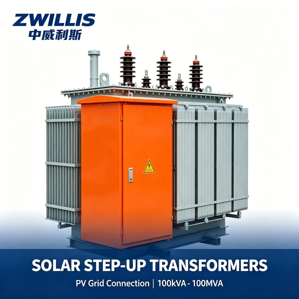
Solar Step-Up Transformers
PV grid-connection step-up transformers from 100 kVA to 100 MVA. Designed for the duty cycle a solar plant actually has — daily start-stop, wide temperature swing, harmonic content from inverters and long periods at partial load.
- Free on-site acceptance, commissioning and training
- One-year warranty from the date of delivery
- Full-wave impulse tested before it ships
A solar plant transformer is energised and de-energised every day, sees a wide day-night temperature swing, and carries inverter harmonics. That duty is different from a distribution feeder and the specification should reflect it.
Capacity 100 kVA – 100 MVA. We supply these as standalone units or integrated into box-type step-up substations — 20 of which went into a 50 MW plant in East Africa generating roughly 80 GWh a year.
- Capacity 100 kVA – 100 MVA for PV grid connection
- Designed for daily cycling and wide ambient temperature swing
- Harmonic-tolerant design for inverter-fed applications
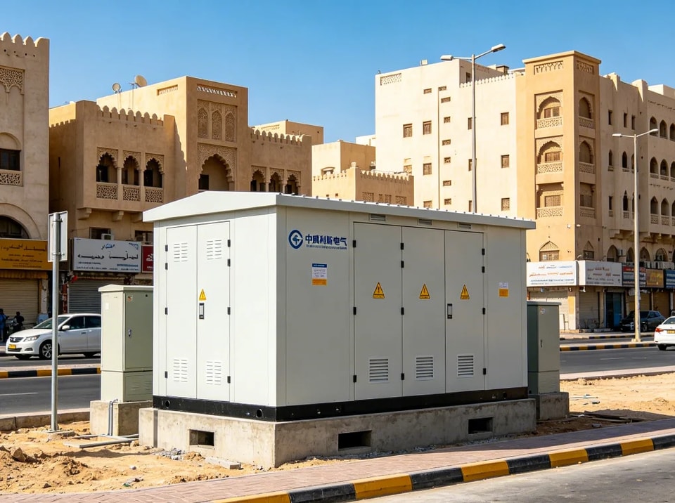
- Available integrated into box-type step-up substations
- IP54 enclosures for dust and moisture at plateau and desert sites
- UV-resistant external finish
Utility-scale solar farms, distributed rooftop and ground-mount PV, and hybrid solar-storage plants.
S10-(50-1600)/35 THREE PHASE DUPLEX WINDING NON-EXCITED TAP-CHANGING DISTRIBUTION TRANSFORMER
| Rated Capacity (kVA) | Voltage Combination and Tap Range | Vector Group Symbol | No-load Loss (kW) | Load Loss (kW) | No-load Current (%) | Short-circuit Impedance Voltage (%) | ||
|---|---|---|---|---|---|---|---|---|
| HV (kV) | HV Tap Range | LV (kV) | ||||||
| 50 | 0.19 | 1.21/1.15 | 2.00 | |||||
| 100 | 0.26 | 2.01/1.92 | 1.80 | |||||
| 125 | 0.31 | 2.38/2.26 | 1.70 | |||||
| 160 | 0.32 | 2.82/2.69 | 1.60 | |||||
| 200 | 0.39 | 3.33/3.16 | 1.50 | |||||
| 250 | 0.46 | 3.95/3.76 | 1.40 | |||||
| 315 | 35 | ±5 | 0.4 | Dyn11 / Yyn0 | 0.55 | 4.76/4.54 | 1.40 | 6.5 |
| 400 | 0.66 | 5.75/5.47 | 1.30 | |||||
| 500 | 0.77 | 6.92/6.58 | 1.20 | |||||
| 630 | 0.94 | 7.87 | 1.10 | |||||
| 800 | 1.11 | 9.41 | 1.00 | |||||
| 1000 | 1.30 | 11.54 | 1.00 | |||||
| 1250 | 1.58 | 13.94 | 0.90 | |||||
| 1600 | 1.91 | 16.67 | 0.80 |
Notes:
Note 1: Rated capacity 500kVA and below transformer, the load loss above the oblique line in the table applies to Dyn11 or Yzn11; the load loss below the oblique line applies to Yyn0.
Note 2: According to requirements, the transformer can supply HV tap change ±2X 2.5%.
Note 3: Outline dimension is designed according to requirements.
S10-(630-31500)/35 THREE PHASE DUPLEX WINDING NON-EXCITED TAP-CHANGING POWER TRANSFORMER
| Rated Capacity (kVA) | Voltage Combination and Tap Range | Vector Group Symbol | No-load Loss (kW) | Load Loss (kW) | No-load Current (%) | Short-circuit Impedance Voltage (%) | ||
|---|---|---|---|---|---|---|---|---|
| HV (kV) | HV Tap Range | LV (kV) | ||||||
| 630 | 0.94 | 7.78 | 1.10 | |||||
| 800 | 1.11 | 9.41 | 1.00 | |||||
| 1000 | 1.30 | 11.54 | 1.00 | |||||
| 1250 | 1.58 | 13.94 | 0.90 | |||||
| 1600 | 35 | 1.91 | 16.67 | 0.90 | 6.5 | |||
| 2000 | ±5 | 3.15 6.3 10.5 | Yd11 | 2.45 | 18.38 | 0.70 | ||
| 2500 | 2.88 | 19.67 | 0.60 | |||||
| 3150 | 3.42 | 23.09 | 0.56 | 7.0 | ||||
| 4000 | 4.07 | 27.36 | 0.56 | |||||
| 5000 | 4.86 | 31.38 | 0.48 | |||||
| 6300 | 5.90 | 35.06 | 0.48 | |||||
| 8000 | 8.10 | 38.48 | 0.42 | 7.5 | ||||
| 10000 | 3.15 3.3 6.6 10.5 11 | Ynd11 | 9.79 | 45.32 | 0.42 | |||
| 12500 | 35~ 38.5 | ±2×2.5 | 11.34 | 53.87 | 0.40 | |||
| 16000 | 13.68 | 65.84 | 0.40 | |||||
| 20000 | 16.20 | 79.52 | 0.40 | 8.0 | ||||
| 25000 | 19.15 | 94.05 | 0.32 | |||||
| 31500 | 22.75 | 112.86 | 0.32 |
Note: Outline dimension is designed according to requirements.
SZ10-(2000-20000)/35 THREE PHASE DUPLEX WINDING ON-LOAD TAP-CHANGING POWER TRANSFORMER
| Rated Capacity (kVA) | Voltage Combination and Tap Range | Vector Group Symbol | No-load Loss (kW) | Load Loss (kW) | No-load Current (%) | Short-circuit Impedance Voltage (%) | ||
|---|---|---|---|---|---|---|---|---|
| HV (kV) | HV Tap Range | LV (kV) | ||||||
| 2000 | 35 | 2.59 | 19.24 | 0.80 | 6.5 | |||
| 2500 | 35 | 3.06 | 20.64 | 0.80 | ||||
| 3150 | 6.3 10.5 | Yd11 | 3.64 | 24.71 | 0.72 | 7.0 | ||
| 4000 | 4.36 | 29.16 | 0.72 | |||||
| 5000 | ±3×2.5 | 5.22 | 31.20 | 0.68 | ||||
| 6300 | 6.34 | 36.77 | 0.68 | |||||
| 8000 | 35~ 38.5 | 8.86 | 40.61 | 0.60 | 7.5 | |||
| 10000 | 6.3 6.6 10.5 11 | Ynd11 | 10.44 | 48.05 | 0.60 | |||
| 12500 | 13.31 | 56.86 | 0.56 | 8.0 | ||||
| 16000 | 14.81 | 70.32 | 0.54 | |||||
| 20000 | 17.51 | 82.78 | 0.54 |
Note: Outline dimension is designed according to requirements.